Easy to operate
Intuitive configuration and device management via drag & drop and graphical configuration elements.
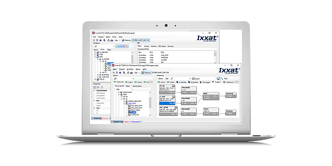
The Advanced Configuration Tool (ACT) is a powerful and easy-to-use PC software package for Windows. The tool is used to create configurations for the Computing Gateways of the Mobilizer, CANnector and FRC-EP series, including Restbus Simulation (RBS) functionality. After having created such a configuration, it is downloaded to the device and being executed standalone.
Intuitive configuration and device management via drag & drop and graphical configuration elements.
Fits to your requirements – available in three different variants that easily expand your specific demands via C user code and/or additional Matlab/Simulink models.
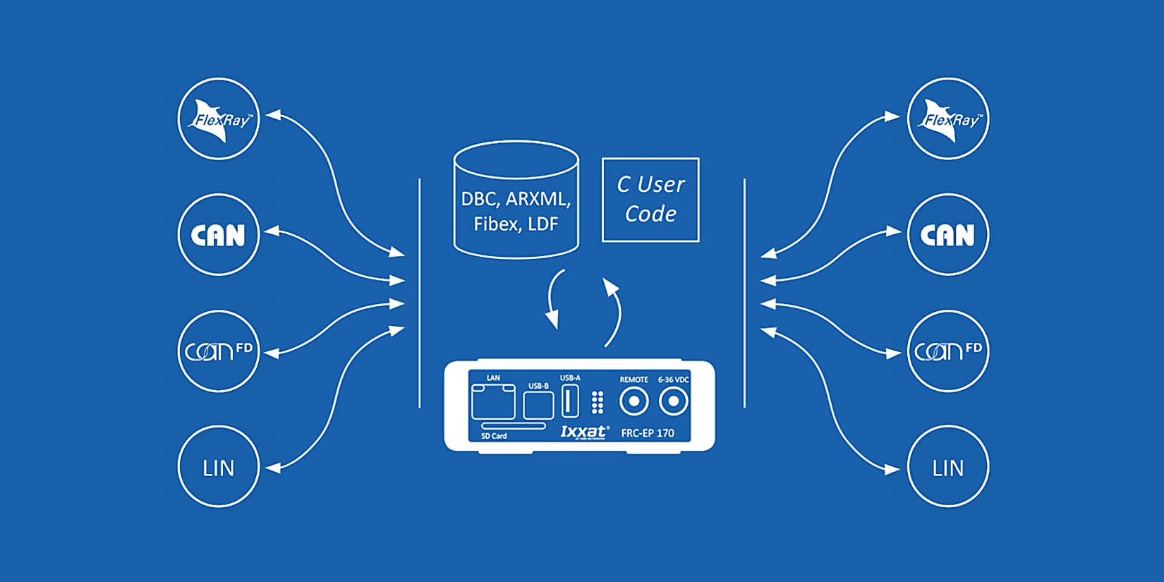
Support of many common database formats, including DBC, LDF, Fibex and ARXML.
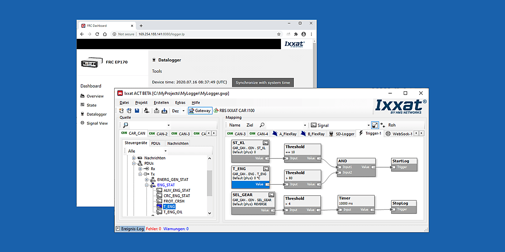
Watch the video to learn how to configure a simple logging device.

How can you configure a gateway application? All you need to do is to use the gateway view of the ACT tool and use the drag & drop concept to define the source and destination relation. Just drag the desired data from the source bus and let it drop on the destination – not relevant whether this is a real bus system or the user code, logger or something else. At the end, the created configuration can be loaded on an Ixxat embedded platform and executed standalone.
Bus description files can be used for these interfaces, but it is not required to use them. If provided, it helps you to easily configure a signal-based gateway because you can select the signals out of the bus description file and map them to another bus with an underlying description file. So, it is thereby possible to combine signals from different source messages into one target message.
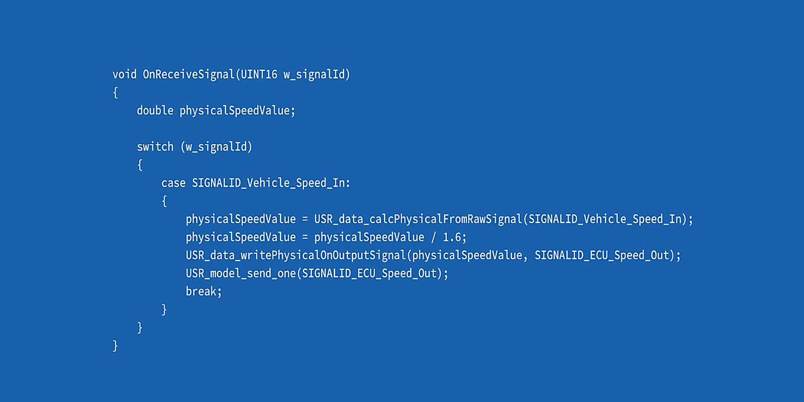
But what if the physical signal representation doesn’t match between source and destination? In this case you can either activate an automatic signal transformation or use your user code or a specific MATLAB/Simulink model to do complex signal adjustments.
And how are the generated frames sent on the destination bus? Therefore, several options are available:
But some signals don’t need a changing value? Yes, that might be the case. In such a case you can use a static default value for these signals. This can be a static value defined in the underlying bus description file or a personally defined value.

Ready !
You need to connect your CAN (FD), FlexRay or LIN based system to modern industrial communication? No problem, just choose a CANnector, Mobilizer or FRC-EP series device with an EtherCAT extension. Inside ACT you can then use the easy drag & drop concept to generate mappings from/to the EtherCAT slave. ACT also automatically generates a corresponding ESI file which can be used together with any capable EtherCAT master to comfortably configure your EtherCAT network.
Once connected to EtherCAT, all data – coming from the CAN (FD), Flexray or LIN bus system or from any other EtherCAT based sensor or IO device – is distributed synchronized and on the same communication system to your SPS or PC controlling the test execution.
The FRC-EP, Mobilizer and CANnector devices do also provide analog or digital I/O ports. ACT allows to use these signals like any other signal in your configuration. After configuration of data direction, range of values, conversion rules and unit, the IOs can easily be mapped via drag & drop from/to any other bus system.
By means of ACT you can add the virtual bus to your configuration. The virtual bus can be used to define your own “variables” (environment variables) in the configuration. These variables can be mapped via the drag & drop concept to/from any other bus system. This allows – for example – to calculate such a variable by your C user code module and then use it in any other bus system.
One functionality of the gateway is to generate DBC Files based on the mapping of the different physical and logical buses – for CAN, CAN FD, Generic Ethernet, virtual CANonEthernet, CAN@net.
XCPonEthernet is too complicated for you? No problem, you can also use the much easier Fast Data Exchange protocol to connect third party software solutions with the CANnector, Mobilizer or FRC-EP series device. With ACT, all needed signals are mapped via the drag & drop concept from/to the FDX bus system. ACT is automatically generating the corresponding XML description file for the FDX bus. This XML file can be imported into your software solution and you are ready to read or send data.
You want to reduce cabling or to bridge large distances? Our Generic Ethernet protocol is easily solving this challenge. Generic Ethernet is a virtual CAN(FD), FlexRay or LIN bus system on Ethernet. By means of ACT you can map the desired data from/to the Generic Ethernet bus system.
The data is then distributed via Ethernet and can be turned back to the physical protocols by using a counter CANnector, Mobilizer or FRC-EP series device. This is called the classical range extender.
In case that you intend to connect the data stream directly to a PC, you can use our VCI driver to use the device as a remote PC interface.
Up to 16 of such virtual buses can be configured. You can use this to distribute the desired data not to one but up to 16 different IP addresses or ports. This means that you can create your own Ethernet based communication network and just use CAN(FD), FlexRay or LIN protocols on the “last mile”.
The Generic Ethernet protocol allows also the combination of Ixxat CAN@net devices with CANnector, Mobilizer or FRC-EP series devices. If you don't have enough CAN ports, just use this possibility to extend to up to 136 CAN / 72 CAN FD interfaces.
Your Windows PC doesn't allow to use the VCI driver? Therefore, the Generic Ethernet protocol is very easy to be implemented on any target operating system. In the easiest case you can just use a terminal program to send and receive the data.
The following work is automatically done by ACT:
All that is done with configuration wizards – there is no programming effort. You want to influence the RBS? No problem, just add your specific code or algorithm into the automatically generated modules. At the end, the complete configuration including your RBS is executed autonomously on the devices of the Mobilizer or FRC-EP series.
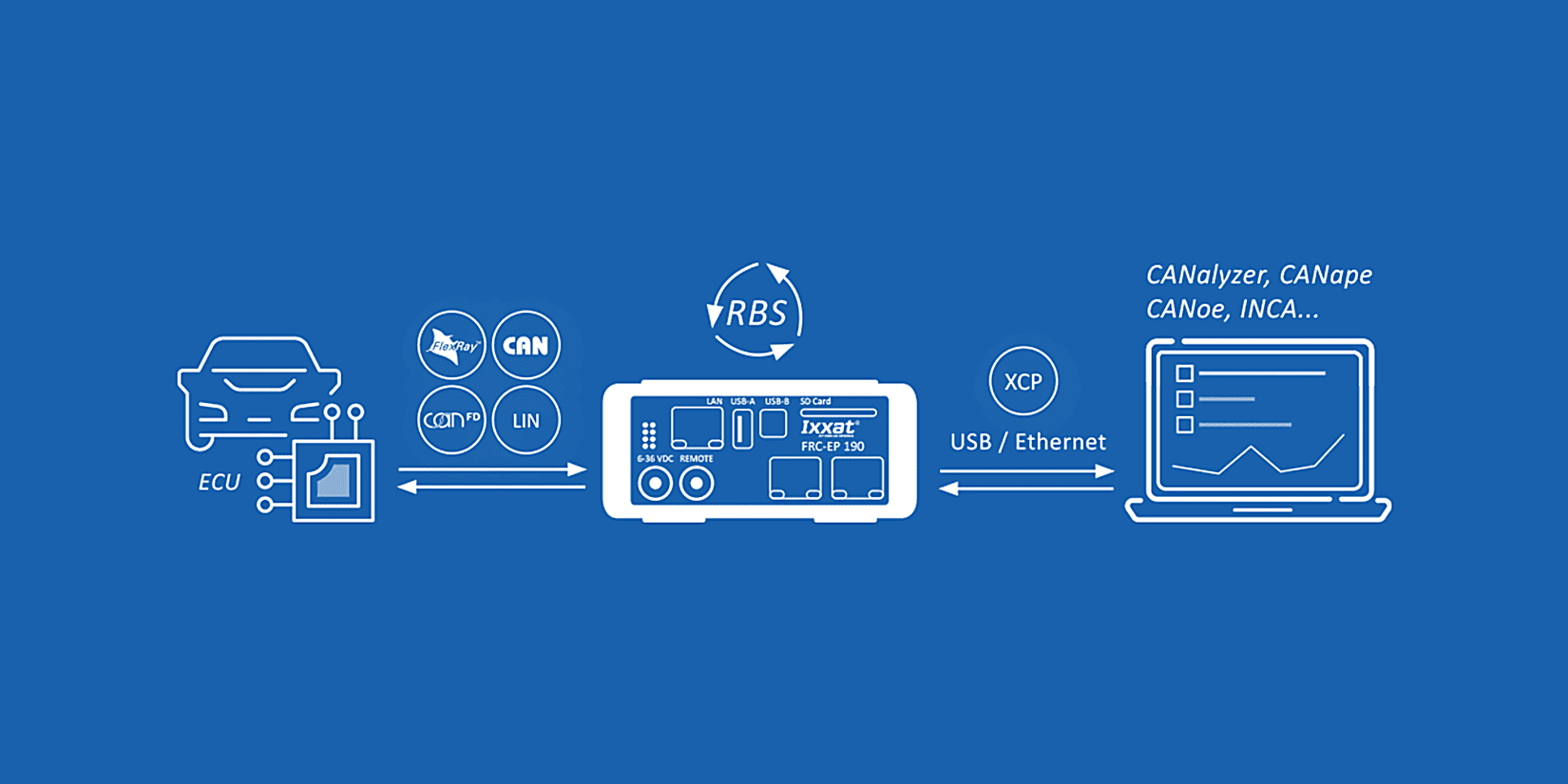
You want to control or adjust the RBS executed on the Mobilizer or FRC-EP series device? For this, XCPonEthernet can be used to connect a third party software supporting this standard.
If needed, ACT generates a A2L description file containing all signals which are sent by the RBS/GW configuration being executed on the device. From the perspective of the third-party tool, the Mobilizer or FRC-EP series device is a virtual ECU. By means of the A2L virtual memory, locations containing the desired signals can be read or written. By doing so, you are able to influence everything that is sent on the different bus systems. This includes also the CRC and alive counters generated by the RBS or signals which a calculated by your user code being executed on the device.
Based on the FlexRay/CAN RBS and the XCPonEthernet extension, the signals sent by the RBS can be defined and manipulated. This includes, for example:
The control of the signal manipulation can take place via user code, the gateway or XCPonEthernet.
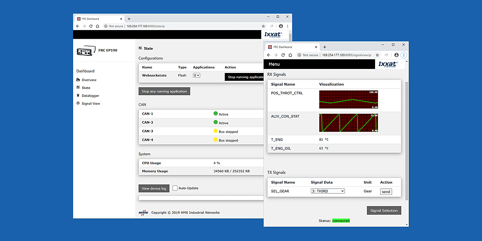
You can individually select which signals shall be visualized and whether they shall be displayed in textual or graphical form. Such a visualization configuration can be stored either on the CANnector/Mobilizer/FRC-EP series or the visualization device. This allows to store views individually or to define by the person having done the configuration what is allowed to be seen.

Do you want to have a specific visualization? If the default visualization is not sufficient, you can easily add your own HTML5 based visualization. You just need to connect to the standardized data exchange stream.
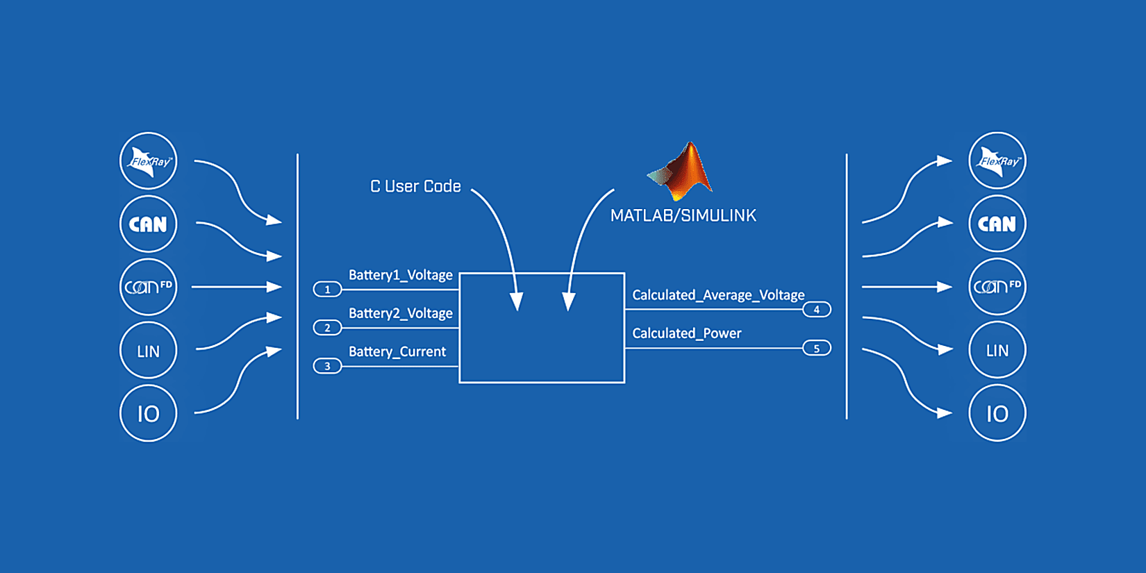
If functional models based on Matlab or Simulink already exist, they can be integrated into the overall configuration using ACT. If required, the ACT automatically generates a basic model that contains all the required signals and the framework for signal transformation from the raw value to the physical signal value. The user only has to design the desired functions using Matlab or Simulink or copy the existing model into the basic model. At the end, the executable module is automatically generated from this model and integrated into the overall configuration, which is executed independently on the device.
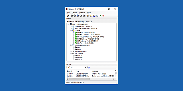
IxAdmin is the PC based administration tool (freeware) for the FRC-EP Series, Mobilizer and CANnector platform which can be connected via USB, Ethernet or WiFi.
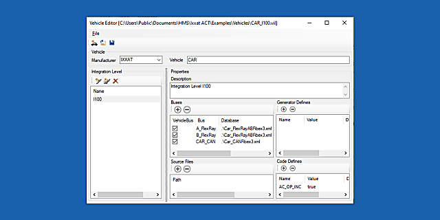
The basis for most solutions are bus description files such as CANdB, DBC, LDF, FIBEX or AUTOSAR-XML. Normally, the descriptions contain a lot of information, but are missing important details like CRC, checksum or alive counter algorithms which are needed to generate e. g. a Residual Bus Simulation (RBS).
The Vehicle Editor allows to create a complete vehicle description database containing all information needed. In case of changes during the life cycle of your testing application (e. g. new vehicle integration levels), a new variant of such a vehicle description database can be created which then allows then an easy porting of existing residual bus or gateway configurations. This saves time and reduces the risk of introducing errors into already verified testing configurations.
| Standard | Lite | Freeware | |
| Product link | Product detail page | Product detail page | - |
| Order number | 1.12.0248.00001 | 1.12.0248.00000 | - |
| IxAdmin | ✔ | ✔ | ✔ |
| Logger | ✔ | ✔ | ✔ |
| Gateway | ✔ | ✔ | ✔ * |
| UserCode | ✔ | ✔ | ✔ |
| Visualization | ✔ | ✔ | ✔ |
| Matlab/Simulink | ✔ | ✔ | - |
| EtherCAT | ✔ | ✔ | ✔ |
| RBS, Signalmanipulation & Error Injection | ✔ | - | - |
| XCP | ✔ | ✔ | - |
| FDX | ✔ | ✔ | - |
| OPC/UA | ✔ | ✔ | - |
* In case of FlexRay RX only