Classic bus/line CAN topology
The Controller Area Network (CAN) high-speed standard specifies the CAN topology as a simple bus (line) with the signal lines CAN-High and CAN-Low, which are terminated at both ends with a 120 ohm terminating resistor.
At the maximum possible bit rate of 1 Mbps, a maximum line length of 40 m can be realized. If possible, stub lines should be avoided, since the signal reflections also affect the signal quality. However, these can be tolerated at a maximum length of 30 cm for the connection of participants.
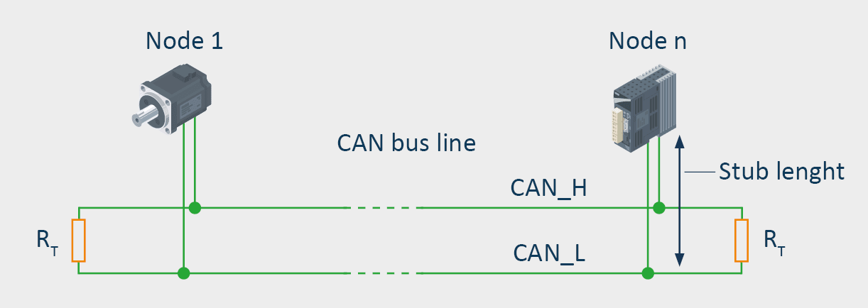
The basic design of the CAN bus with CAN-High (CAN_H) and CAN-Low signal line (CAN_L) as well as termination at both ends.
Due to the bus topology, long line lengths can quickly be reached, depending on the spatial situation. The following example shows a CAN bus system where a bus length of 330 meters is reached due to the bus being looped through to all participants. On a system of this length, the maximum bit rate would be 125 kbps.
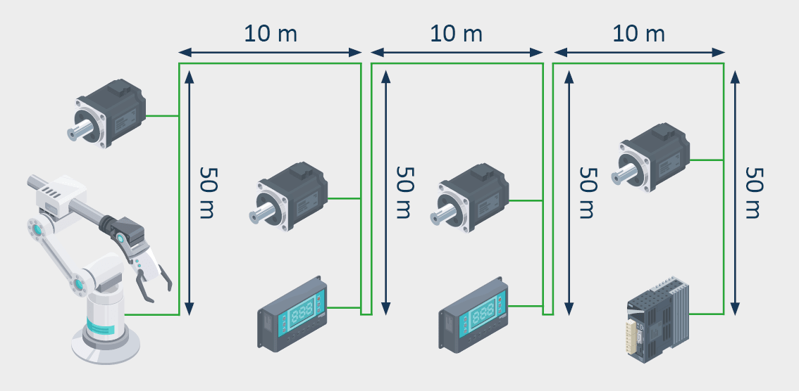
Conventional wiring of the CAN participants according to the bus/line topology
Greater flexibility due to the tree/star CAN topology
Repeaters can be used to expand the simple CAN line topology and to realize tree/star CAN topologies that are optimally adapted to the geographic framework conditions. The repeater provides a physical coupling between two identical bus systems. It is used to regenerate signals and transparently pass them on to the respective other segment. A repeater thus divides a bus into two segments that are physically independent of each other. From a signaling viewpoint, it corresponds to a line whose length equates to its delay time.
Thanks to a clever arrangement of the repeaters and an optimal line routing that is achieved in this way, the relevant length of the bus system, i.e., the distance between the farthest removed participants, can be reduced. In the following example, while taking the signal delay generated by the repeater (corresponding to a line length of 50 m) into account, the furthest distance between the participants is 170 m. The use of repeaters thus considerably reduces the line length, which means the system can operate with a bit rate of up to 250 kbps, improving the signal quality.
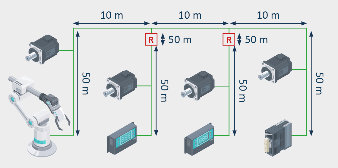
System optimization by using CAN repeaters
Maximum flexibility with bridges and gateways
CAN bridges have a storage function and forward messages or parts of messages in an independent, time-delayed transmission (store-and-forward principle). They differ from repeaters by saving and forwarding messages or parts of messages, whereby repeaters transmit electrical signals to the other segment.
Integrating filter functions, for example, allows for organizational structuring of a network by only forwarding messages from one network segment to another, which are of interest to it. This can, for example, reduce the bus load of segments.
The system range can easily be expanded, since the use of a bridge can divide the CAN network into two systems that are independent of each other as regards signaling.
CAN gateways can be used to connect networks of different protocols with each other. A gateway application takes over the translation of protocol data units here into the respective other communication system. The protocol level at which the protocol translation takes place is identified by the gateway.
Using gateways allows both the coupling of a CAN-based system with other fieldbuses, as well as the coupling of two CAN-based systems via a transparent TCP/IP tunnel. In this way, far-removed CAN systems can be coupled with each other, or different fieldbuses can be connected to each other in order to connect these to a higher-level control system, for example.
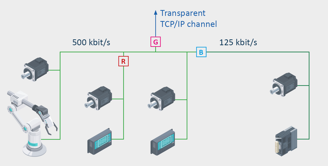
The use of a CAN bridge to connect a CAN segment with a lower bit rate as well as the connection to a distant CAN system via CAN-Ethernet/CAN gateway and transparent data transmission via TCP/IP.
Summary
The development of traditional bus/line CAN topology to advanced tree/star topologies and the use of technologies, such as repeaters, bridges, and gateways is a significant evolution in the design and functionality of CAN networks. These make it possible to bridge longer distances, to achieve higher data transmission rates, and to facilitate the integration of different communication systems. This significantly increases the efficiency, reliability, and adaptability of CAN-based systems in different application areas.

