Current trends in manufacturing focus on the use of Information and Communication Technologies (ICT). This has evolved over the years but is of course also driven by initiatives such as Industry 4.0. New production systems will more and more have a synergy between conventional production technology as well as ICT, allowing machines and products to exchange information, trigger actions, and control other components autonomously.
This means that seamless communication between physical objects of the production floor and various computer systems is required. In such systems, a major goal is to enable communication of Industry 4.0 products among each other via industrial networks and use OPC UA and the OPC UA information model to represent the static and dynamic behavior of the manufacturing systems. The virtual representation and grouping of data for each product or manufacturing system will simplify structures and virtual models and give access to more important data, which leads to faster and easier control and maintenance of the production systems.
The OPC Foundation has based on input and in collaboration with the industry and the major suppliers of production equipment realized the specification of the OPC UA information model and related companion specifications.
OPC UA and functionalities such as the OPC information model will more and more become a requirement from the industry and can now in a fast and easy way be enabled in the Anybus CompactCom series.
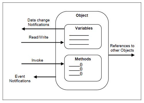
An information model in OPC UA is built up by objects. An object can contain variables and methods and reference other objects. The variables can be accessed by clients by read and write operations. Methods can be invoked by clients and are then executed by the server. Clients can also subscribe to data change notifications from variables and to event notifications from the object itself.


Figure 1 Logic view of an OPC UA object
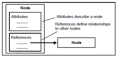
The building blocks to realize an object in an OPC UA information model are Nodes. A node consist of a set of attributes and a list of references as shown in Figure 2. The attributes are used to describe a node and the references to reference other nodes. To realize an object consisting of variables and methods multiple nodes are used. The object itself and every variable and method of an object is represented by nodes. References are used to bind these nodes together to an object.

Figure 2 OPC UA node
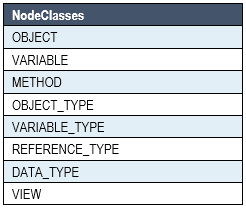
Nodes are divided into eight classes (Table 1). All node classes share a common set of attributes and extends those with class specific attributes. Each node class can also specify requirements on what references that can or must be present.

Table 1

OPC UA Modeler Tool
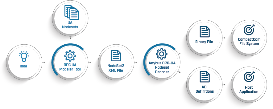
The OPC UA Modeler tool is a software tool that allows users to create, modify, and export OPC UA information models. The OPC UA Modeler Tool can be any existing modeler tool on the market, there are several available, that uses standard OPC UA Nodeset files as input to the application. All the configuration needed for your specific OPC UA information model is setup in this tool based on the companion specification required. The OPC UA Modeler Tool exports a standard formatted Nodeset2 file that can be read by the Anybus OPC UA Nodeset Encoder to generate the files for the Anybus CompactCom module.
The Nodeset2 XML format is specified by OPC Foundation and is the standard machine-readable format to describe an OPC UA information model. This format is future proof interface between the host application developer and our tool as it is part of the OPC UA specification and is expected to be maintained by OPC Foundation for future updates of OPC UA. This interface also allows you as a customer to freely choose any method and tool to generate the Nodeset2 XML file. There are a few open source and licensed tools available on the market that should be sufficient to generate the Nodeset2 XML file. These tools can be recommended by HMS.
Anybus OPC-UA Nodeset Encoder
The purpose of the command line tool is to transform the Nodeset2 XML file to a binary file that is more compact and less resource intensive for the CompactCom 40 module. The command line tool will take the Nodeset2 XML file as input and then generate the following files as output
The binary file is then downloaded to the ftp server of the Anybus CompactCom and the ADI mapping and example code is used in the application code.